
Comparisons between numerical and experimental
mixing in Stirred Tanks
For more information, see this link.
Figure 1 - Single pitched blade impeller in viscous fluid. Left: experimental
visualization of non-mixing regions. Right: computational comparison.

Figure 2 - Comparison between experimental and computational (inset)
surfaces of section from flow in Fig. 1.
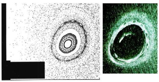
Figure 3 - Enlarged view of island above impeller. Note small island
chain surrounding
main island in both simulation (left) and experiment (right).

Figure 4 - Comparison between experimental (Particle Image Velocimetry:
Dantec)
and numerical (Computational Fluid Dynamics: Acusim) velocity fields near
impeller.